| View previous topic :: View next topic |
| Author |
Message |
lazarvlad
Junior 2

Joined: 23 Feb 2012
Posts: 41
|
 Posted: 29/08/2014 10:50 Post subject: Tank Calibration Posted: 29/08/2014 10:50 Post subject: Tank Calibration |
 |
|
Hello guys,
I have some problems with my new project, this project is in the marine industry, and more exactly it is automation for a boat.
Customer wants when calibrate the level in tank to have a nonlinear parameterization (curve) in at least 20 points.
Did someone something? An example I would be very helpful, or at least some ideas are welcome.
Attached you will find two screens as the trend should look like and what data should be used.
Thank you for any information or advice.
[url=http://www.99poze.ro/p/cb29da8400f90799ef78b132241099fa.jpg]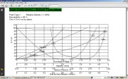 [/url]+[url=http://www.99poze.ro/p/d7524ee8b033c2979b06ef5a554a384a.jpg] [/url]+[url=http://www.99poze.ro/p/d7524ee8b033c2979b06ef5a554a384a.jpg]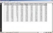 [/url]+ [/url]+ |
|
| Back to top |
|
 |
rott
Senior

Joined: 23 Aug 2011
Posts: 2266
|
| Posted: 29/08/2014 18:43 Post subject: Re: Tank Calibration |
|
|
| lazarvlad wrote: | Hello guys,
I have some problems with my new project, this project is in the marine industry, and more exactly it is automation for a boat.
Customer wants when calibrate the level in tank to have a nonlinear parameterization (curve) in at least 20 points.
Did someone something? An example I would be very helpful, or at least some ideas are welcome.
Attached you will find two screens as the trend should look like and what data should be used.
Thank you for any information or advice.
[url=http://www.99poze.ro/p/cb29da8400f90799ef78b132241099fa.jpg][/url]+[url=http://www.99poze.ro/p/d7524ee8b033c2979b06ef5a554a384a.jpg][/url]+ |
Here is an example for using PID Compact for level control:
http://www.datafilehost.com/d/91c9df1b
and a Matlab schematics
http://www.datafilehost.com/d/4f6ac2c7
What you have to do:
Use feedback from the level sensor and transpose the signalin a look-up table whith your values from the table.
Another method is to use in Matlab a polynomial function which approximate your curve and transform the feedback through this function.
Take a look on some helping materials:
http://www.posterus.sk/?p=12560
http://www.lmnoeng.com/Volume/CylConeSphere.php
It's necessary a schematic diagram of your system for a better response. |
|
| Back to top |
|
|
rott
Senior
Joined: 23 Aug 2011
Posts: 2266
|
| Posted: 29/08/2014 18:51 Post subject: Re: Tank Calibration |
|
|
| lazarvlad wrote: | Hello guys,
I have some problems with my new project, this project is in the marine industry, and more exactly it is automation for a boat.
Customer wants when calibrate the level in tank to have a nonlinear parameterization (curve) in at least 20 points.
Did someone something? An example I would be very helpful, or at least some ideas are welcome.
Attached you will find two screens as the trend should look like and what data should be used.
Thank you for any information or advice.
[url=http://www.99poze.ro/p/cb29da8400f90799ef78b132241099fa.jpg][/url]+[url=http://www.99poze.ro/p/d7524ee8b033c2979b06ef5a554a384a.jpg][/url]+ |
What type of transmitter do you use ..because some transmitters has some functions for linearized the non-linear curves. |
|
| Back to top |
|
|
rott
Senior
Joined: 23 Aug 2011
Posts: 2266
|
| Posted: 29/08/2014 19:11 Post subject: |
|
|
Try to use this converter if you are using TIA Portal programming.
http://plc.myforum.ro/viewtopic.php?p=13700#13700 |
|
| Back to top |
|
|
rott
Senior
Joined: 23 Aug 2011
Posts: 2266
|
| Posted: 30/08/2014 14:32 Post subject: |
|
|
TIA V11 look up example:
http://www.datafilehost.com/d/46370eaa |
|
| Back to top |
|
|
rott
Senior
Joined: 23 Aug 2011
Posts: 2266
|
| Posted: 30/08/2014 15:06 Post subject: |
|
|
What is the significance of the initial and actual values of a data block?
Description
The name for variables, the data type, a commentary and an initial value are configured in the declaration table for a data block. This initial value is a pure configuration variable which is applied as an actual value when generating a data block on the basis of a UDT (user-defined data type) or in a declaration for a new variable in a global data block. The actual values become visible via the menu commands "View > Data view".
The initial value is only configured once for a data block or for a newly declared variable data block. If the variable already exists, the actual value is unaffected by any change in the initial value. The only value of significance to the CPU is the value in the column headed "Actual value". Even if the initial value is also loaded onto the CPU and can be monitored there in online mode, this value is not used by the CPU.
You have two options for starting your CPU with a new value:
Switch to the data view and enter your new initial value in the "Actual value" column.
Go to the declaration view and enter your new initial value in the "Initial value" column. Then switch to the data view. You can then transfer all the values from the "Initial value" column to the "Actual value" column via the menu command "Edit > Initialize Data Block".
Then load the data block into the CPU.
Since the initial value does not continue to use the initial values, there is no need to perform the opposite procedure, i.e. to load the values from the "Actual value" column to the "Initial value" column. There is no menu command for this either in STEP 7. The following instructions are used in some uncommon configurations for saving the actual values of a data block as initial values. This procedure can either be conducted directly within an STL source or by saving the values with Excel.
Saving the actual values of a data block as initial values directly in the STL source
Once the STL source has been generated, the actual values can be copied line-by-line into the declaration lines in the STL source.
No. Procedure
1 Select the online view in the SIMATIC Manager via "View > Online" and open the data block within the online view. Save the data block either by clicking the floppy disk button or via "File > Save".
2 Create a source for the data block via "File > Generate Source...".
3 Open the source, which you have generated, in the source folder in the SIMATIC Manager.
4 In the STL source, copy the actual values, which are positioned between "BEGIN" and "END_DATA_BLOCK", line-by-line into the corresponding declaration lines (initial values) after the corresponding data types.

Fig. 01
As Fig. 01 shows, you have to copy the actual values with the assignments ":=" into the declaration lines of the initial values. As a result, the declaration lines are defined as shown in the example below:
Data_1 : BYTE := B#16#AA;
5 Save and compile the STL source via
File > Save
File > Compile
The actual values are then applied as initial values.
Saving the actual values of a data block as initial values with Excel (the convenient way)
The actual values of a data block can also be saved in Excel as initial values. This option is particularly advisable for large data blocks because the data is copied into the declaration lines in a block here, not line-by-line. The table below explains what you need to watch out for when importing and exporting the STL source and when saving in Excel.
No. Procedure
1 Select the online view in the SIMATIC Manager via "View > Online" and open the data block within the online view. Save the data block either by clicking the floppy disk button or via "File > Save".
2 Create a source for the data block via "File > Generate Source...".
3 Mark the generated source in the source in the SIMATIC Manager and right-click it. Then select the "Export Source..." command in the pop-up menu.
4 Select "STL source (*.awl)" as the file type in the "Export source" dialog box, as well as the folder where the source is to be exported. The file name must contain the file extension ".AWL", e.g. "Source_DB2.AWL". Then click the "Save" button.

Fig. 02
5 Start Microsoft Excel and open the exported STL source via "File > Open...". The "Text-import Wizard" dialog opens.
Note
You have to select "All files (*.*)" as the file type in order to ensure that the STL source is visible in the "Open" dialog box.
6 In step one of the text-import wizard, enable the "Delimited" formatting option.

Fig. 03
Then click on the "Next" button.
7 In the next dialog box of the text-import wizard, select "tab" or "space" as the delimiter.

Fig. 04
Then click on the "Next" button.
8 In the third step of the text-import wizard, select "standard" as the data format for the columns.

Fig. 05
Then click on the "Finish" button. The converted STL source is now opened in Excel.
9 Select all the cells belonging to the STL source in Microsoft Excel and right-click. Then select the "Format Cells..." command in the pop-up menu.

Fig. 06
10 Select "Right" or "Right (Indent)" as the horizontal text alignment in the dialog box "Format Cells > Alignment" and click OK to confirm.

Fig. 07
11 Now select the actual values between "BEGIN" and "END_DATA_BLOCK", including the assignments ":=", and copy the data into the declaration lines between "STRUCT" and "END_STRUCT" after the corresponding data types, as shown in Fig. 08.

Fig. 08
12 Then check whether the syntax agrees after copying the actual values into the lines for the initial values. Example:
STRUCT
Data_1 : BYTE := B#16#AA;
...
END_STRUCT;

Fig. 09
13 Save the file in Excel via "File > Save as..." and select
Formatted Text (Space delimited)(*.prn) as the file type.
Note
Once you have saved the file as described above, you receive the file, e.g. "Source_DB2.AWL". However, if you save the file under another name, such as "Source_DB20.AWL", the file "Source_DB20.AWL.PRN" will be stored on your system. This file then has to be renamed from "Source_DB20.AWL.PRN" to "Source_DB20.AWL" (delete the extension PRN). The extension "PRN" has been added by the system in cases where the file name ending "AWL", which is being saved, has already been entered once.
14 Import the STL source, which you processed in Excel, into the source folder for your STEP 7 project in the SIMATIC Manager via "Import > External Source...".
15 Mark the imported STL source in the source folder and right-click. Then select the "Compile..." command in the pop-up menu. The actual values are saved as initial values following compilation.

Fig. 10
Note
If you use UDTs in your data block, there is a restriction here. You cannot attach the actual values to the variables as initial values. While the UDTs can be exported, any change in the initial value of the UDT affects all (!) the places where the UDTs are used equally. Distinctions cannot be made between the places where it is used. |
|
| Back to top |
|
|
rott
Senior
Joined: 23 Aug 2011
Posts: 2266
|
| Posted: 30/08/2014 15:16 Post subject: Range and Level Measurement in the S7-CPU using a Sonar BERO |
|
|
Range and Level Measurement in the S7-CPU using a Sonar BERO

The process sequence works as follows:
A Sonar BERO measures the distance to the surface of the respective medium. This information (current 4 to 20 mA) reaches the S7-CPU via an analog input. There, the current filling level is determined. It is visualized on a TP170A touch panel. The STEP7 code additionally offers you the possibility of defining seven filling sections by specifying eight reference levels, within which certain actions can be performed (e.g. setting digital outputs). Furthermore, limit level violations (container = empty, full) are displayed at the touch panel. Underrun or overrun represents an alarm which requires acknowledgement. The acknowledgement is performed alternatively via a digital input or via the TP170A.

https://cache.automation.siemens.com/dnl/zc/zc1MTM4OQAA_23509834_Tools/23509834_Abstand_Fuellstand_V20_e.pdf
https://cache.automation.siemens.com/dnl/DU3NDA3AAAA_23509834_apps/23509834_Abstand_Fuellstand_V20.zip |
|
| Back to top |
|
|
rott
Senior
Joined: 23 Aug 2011
Posts: 2266
|
| Posted: 30/08/2014 15:49 Post subject: |
|
|
Interpolation 1D, 2D, 3D
http://www.datafilehost.com/d/4057a1f6 |
|
| Back to top |
|
|
lazarvlad
Junior 2
Joined: 23 Feb 2012
Posts: 41
|
| Posted: 31/08/2014 13:21 Post subject: |
|
|
| rott wrote: | Interpolation 1D, 2D, 3D
http://www.datafilehost.com/d/4057a1f6 |
Thank you very much for this information and documentation rott, it's very helpful for me. |
|
| Back to top |
|
|
dani_val
Member junior

Joined: 27 Mar 2013
Posts: 75
|
| Posted: 21/10/2014 22:34 Post subject: |
|
|
| Awesome! |
|
| Back to top |
|
|
trak
Member junior
Joined: 24 Apr 2015
Posts: 62
|
| Posted: 06/06/2015 12:50 Post subject: |
|
|

https://www.linkedin.com/pulse/liquid-volume-horizontally-mounted-cylindrical-tank-thomas-scharmann

Calculate the fraction of the circle's area that is the circle's segment ACE
Taking Equation R and dividing it by Equation A provides the fraction of the tank's volume that contains liquid.

Calculate the volume in the tank
Multiplying Equation S by the global volume capacity of the tank provides the liquid volume of the tank.

Equation T is the formula to be used in code. Replace h with the level transmitter's output, not forgetting to account for units, and the output will be the liquid volume.
https://docs.google.com/spreadsheets/d/1c9rrqP7Xd1JeEx6E3ud3U61tROoxbgWeTzurwsB7-0I/edit#gid=0 |
|
| Back to top |
|
|
|

 FAQ
FAQ Search
 Memberlist
 Usergroups
 Register
 Profile
 Log in to check your private messages
 Log in


