| View previous topic :: View next topic |
| Author |
Message |
nhoskonvt
Junior

Joined: 22 Aug 2016
Posts: 3
|
 Posted: 14/08/2018 09:26 Post subject: PLC CJ2M-CPU35 Communicate with Other manufacturer PLC Posted: 14/08/2018 09:26 Post subject: PLC CJ2M-CPU35 Communicate with Other manufacturer PLC |
 |
|
Hi forum,
I have a question relatived to communication between CJ2M-CPU35 and PLC Siemens by Ethernet IP (CJ1M-EIP21).
As I found a document (W465), that describes we can transfer explicit data by using command CMND(490).
But the code example makes me quite confused.
Is there anyone have experience on this?
If can, please help to send me an example code.
I would appreciate that.
Thank you so much, everyone. |
|
| Back to top |
|
 |
belzox
Junior
Joined: 06 Aug 2018
Posts: 8
|
| Posted: 14/08/2018 20:55 Post subject: Re: PLC CJ2M-CPU35 Communicate with Other manufacturer PLC |
|
|
| nhoskonvt wrote: | Hi forum,
I have a question relatived to communication between CJ2M-CPU35 and PLC Siemens by Ethernet IP (CJ1M-EIP21).
As I found a document (W465), that describes we can transfer explicit data by using command CMND(490).
But the code example makes me quite confused.
Is there anyone have experience on this?
If can, please help to send me an example code.
I would appreciate that.
Thank you so much, everyone. |
Your Siemens CPU supports Profinet communications?
What Siemens CPU do you use?
For your information you can use
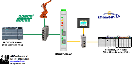
http://www.adfweb.com/home/products/PROFINET_EtherNetIP.asp
CJ2M-CPU35 use EtherNetIP communication.
Most of the Siemens CPU are PROFINET enabled.
So the PROFINET / EtherNetIP - Converter is a necessary way..
More details..???
Last edited by belzox on 15/08/2018 17:32; edited 1 time in total |
|
| Back to top |
|
|
nhoskonvt
Junior
Joined: 22 Aug 2016
Posts: 3
|
| Posted: 15/08/2018 05:49 Post subject: Re: PLC CJ2M-CPU35 Communicate with Other manufacturer PLC |
|
|
The configuration I am using is CPU 416-3 and one CP443-1 (6GK7 443-1EX20-0XE0).
Is that possible to connect to Omron PLC CJ2M-CPU35 by Ethernet directly without converter? |
|
| Back to top |
|
|
nhoskonvt
Junior
Joined: 22 Aug 2016
Posts: 3
|
| Posted: 15/08/2018 18:25 Post subject: |
|
|
Hi belzox,
I really appreciate for your help.
I will try it.
Thank you so much |
|
| Back to top |
|
|
LongSh
Junior
Joined: 15 Aug 2018
Posts: 1
|
| Posted: 15/08/2018 18:37 Post subject: |
|
|
Hi belzox,
Regarding to this topic, I have a job need to make communication between CJ2M-CPU31 and Fuji Micrex-SX NP1PM-256E by Ethernet also.
The Micrex-SX PLC has built-in Ethernet IP port, same like CJ2M-CPU31 PLC, so is that possible to do the interface (may use explicit message)?
I read on Omron manual for example code but it's quite hard to understand. (because I don't have much experience on Omron PLC). I'm so stressful now:(
Do you have any example code on Omron side? I would appreciate for your help.
Thank you. |
|
| Back to top |
|
|
belzox
Junior
Joined: 06 Aug 2018
Posts: 8
|
| Posted: 15/08/2018 20:34 Post subject: EtherNet/IP Network Between 2 CJ2M PLCs |
|
|
In the download file you can watch on how to setup an EtherNet/IP Network Between 2 CJ2M PLCs maybe help you.
The video files show the following items:
Creating a CX-Programmer project with two CJ2M CPU's to set IP addresses and transferring to the controllers (1_EIP_cx-p(engsub).avi)
Creating a configuration in Network Configurator for EtherNetIP (with and without the Wizard) and transferring (2_EIP_Network_Config(engsub).avi)
Exporting tag sets from Network Configurator for EtherNetIP and importing them into CX-Programmer (3_Export_network_tag_EIP_NC_to_CX-P(engsub).avi)
Creating network symbols/variables in CX-Programmer and tranferring them into Network Configurator for EtherNetIP (4_Export_network_tag_CX-P_to_EIP_NC(engsub).avi)
The diagram on how it is to be connected:

These four movies have been made with CX-One v4.
https://nofile.io/f/e4zEMr4g9M0/EtherNetIP+Network+Between+2+CJ2M+PLCs.rar
I didn't work with Fuji so I cannot help you further in this clipă |
|
| Back to top |
|
|
belzox
Junior
Joined: 06 Aug 2018
Posts: 8
|
| Posted: 15/08/2018 20:49 Post subject: How To Setup EtherNet/IP Datalinks |
|
|
How To Setup EtherNet/IP Datalinks
Configure EtherNet/IP Datalinks between Omron PLCs with an EtherNet/IP interface. EtherNet/IP Datalinks are a fast and easy way to exchange even large amounts of data between PLCs. The Datalinks use the Producer/Consumers principle. One device is sourcing the data and one or more can receive the data. A network technology called IGMP is used to send data to multiple devices with one message.
This introduction explains some important terminology and concepts that appear throughout the guide:
Tag: is a name given to one block of data. It can be a network symbol or a piece of PLC memory with start-address and length. It can be input, output or publication (when the variable is being shared with a device other than a PLC).
Tagset: set of tags to be used in a communication link.
Communication links: links between Tag producers and Tag consumers.
In-Consume: input tag, or tag that the PLC "consumes" from the "producer" PLC
Out-Produce: output tag, or tag that the PLC "produces" to the "consumer" PLC.
Multicast Connection: by transmitting one single message, information is sent to numeroase nodes. Multicast in EtherNet/IP uses IGMP (Internet Group Management Protocol) to transfer data to selected nodes in an efficient way.
Point-to-Point Connection requires the transmission of a message to each individual node.
Performance parameters of Omron EtherNet/IP interfaces:

Note: There has been a firmware update for the CJ2M EtherNet/IP built in interface. The initial version supported 32 connections with a maximum size of 20 words each. This is a total of 640 words. However often the maximum size of 20 words was to small to fit the application. Therefore a change in firmware was made where still the total limit of 640 words and 32 connections exists. But the maximum size of a connection was now set to 640 words.
The EtherNet/IP Datalink Tool
The easiest way to create data-links between Omron CJ and CS types PLCs equipped with an EtherNet/IP interface is through the EtherNet/IP Datalink Tool.
What the tool does is creating Tagsets in each PLC where there is one producing and as many consuming as there are other PLCs. Each PLC can have two datalink areas with a certain start-address and size per tagset. In every area the tagsets are of the same size. The first PLC produces the first tagset, the others are receiving data here. The second PLC produces the second tagset, the others are receiving data from the second PLC here. And so on.
The table below is a global overview of all the tagsets created and how they are transferred between the different PLCs.

In this example we set up 5 PLCs to share data through datalinks.
They should already be set up to communicate on the network to be able to download to the PLCs the made configuration.
The EtherNet/IP Datalink Tool is started from the Menu bar by selecting Network/EtherNetIP Datalink Tool

When the EtherNet/IP Datalink Tool is started first the Datalink Wizard will appear. Here the memory area, start address and sizes of the tagsets can be set. Let’s use the values as shown in the global overview. So area 1 starts at W0 and each tagset is 50 words in size. The second area starts at D50 and each tagset is 100 words in size.

The Enable Output Inhibit can be used to set a tagset area to zero if the communication to that PLC fails. This can be used as a kind of safety measure but it depends on your application.
After pressing OK the wizard will populate all PLCs with new tagsets and connection information. All previous entered information will be discarded.
The EtherNet/IP Datalink tool has now created the necessary structure. You will see that each PLC has only one Output area and multiple input areas.
For PLC1

For PLC2

And so on till PLC5.

Now Save and Close the DataLink Tool.
From here we can go online on the network and download the configuration to the PLCs. The data-exchange will start automatically.
However we can have a look at what the EtherNet/IP Datalink Tool actually did.
Double-click on PLC and its Device Parameters edit screen will appear.

You see that it has four connections, one to each of the other PLCs. All the other PLCs have the same.
You will also find in every PLC 4 consuming and 1 producing Tagsets.
A tagset consists of the tags PLCStatus and the ones for Area 1 and Area 2 as set in the Datalink Wizard. Area 1 is here in W-memory with a size of 50 words / 100 bytes. The Area 2 tag is in D-memory and each tag is then 100 words / 200 bytes in size.
Notice that PLCStatus, the W-memory and the D-memory are assembled to one big tagset that has a size of 302 bytes. And this is the amount of data that is sent over in one EtherNet/IP message.


Next to the size of the data there is also information on the Requested Packet Interval (RPI) and the type of Connection that is used to transfer the data. Press the Hide/Show detail button to show the RPI information.
By default the RPI is set to 50 ms and the Connection type is set to Multi-cast. More on Multi-cast is in the chapter: Multi-cast connections and IGMP.
Should data be transferred in a higher rate then the RPI can be changed for these. It is even possible to set per connection. Maybe PLC1 needs the data from PLC2 at a higher rate. The Packet Rate can be changed here:

However the Packet Rate can be changed for all connections at once. In the main overview of the Network Configurator there is a Usage of Device Bandwidth Detail button.

An overview is shown with the total capacity of the EtherNet/IP unit used, the total Mbit/s this will take and the amount of IP-Multicast connections this will take. Make sure not to go over the maximum of 100% of the capacity or the Mbit/s maximum (10 or 100 Mbit/s) of your Ethernet connection speed.
The values between brackets show you the values when no Mulitcast filtering is used.
Multicast filtering is a functionality of the Ethernet switches used in the network and need to be set within the Ethernet switch.


The RPI is changed for the PLCs selected.
When you are satisfied with the settings then go online and download the configuration to all PLCs.
Multi-cast and IGMP.
To transfer data efficiently over the network EtherNet/IP can make use of Multi-casts. The principle of operation is that the producing PLC is sending out only one message that is received by a group of other PLCs. Not to all PLCs as this could be an overload on the network.

The technology used for this is IGMP or Internet Group Management Protocol.
The IGMP protocol is developed to serve video-streaming or gaming over the Internet. The devices in such Multicast structure are one Server, Routers to route the messages properly and Clients as the end points. The Clients enlist themselves in an IGMP-group by sending a group-join request.

A switch uses IGMP-snooping to learn to which group this Client wants to get messages from. If it then receives IGMP-messages for this group then the switch will forward this message to the proper port according to what it learnt through its IGMP-snooping.
As IGMP is a Level 3 service it is commonly only supported by managed switches. For level 2 un-managed switches an IGMP-message is just a broadcast message and it will forward an IGMP-message to all its ports. That is just what IGMP is all about. An incoming message should only go out on those ports where it needs to go out as the connected device has asked for it.
In the example, with the five PLCs and Multi-cast set, it only takes five messages to update all PLCs. As each PLC wants to receive data from four different PLCs it sends out four IGMP-group joins to notify switches it is interested in data from a certain IGMP-group / Server.
Actually the IGMP-group is just a specific IP-address in a certain reserved IP-range.
What happens if no managed switches are used depends on your application.
If you have a network with only these EtherNet/IP devices, like our example with the 5 PLCs, then although all messages will be coming out of all ports but no other devices will be bothered with it. The PLCs will receive all the messages they want.
In case you have other devices on the network then they will also receive the EtherNet/IP messages. As it is a broadcast the device need to work on the message and need to decide what to do with the message. Normally they drop the message but it is in any case a burden on the processor of the device.
And remember the messages will be coming in a fixed interval (the RPI) and then from all producers. This can be quite a lot of interrupts per second on this device. In our example it are every 50ms 5 messages. Is 100 interrupts a second. This could be enough to crash a badly designed device.
A remedy would be to change from Multi-cast to Point-to-point. Now every producer will sent to every consumer separately a message. This will increase the number of messages to be sent, in our example a factor of 4, but layer2 switches know to which port the message should be forwarded to.
Therefore in a system where also other devices are connected to the Ethernet network it is advisable to use managed switches or Level 3 switches. They check the IP-part of the message to see how to forward the message. They are equipped to handle IGMP properly.
Conclusion
It is very easy to set up data-links between PLCs with an EtherNet/IP interface by the Network Configurator for EtherNet/IP. However be aware about the amount of traffic that is generated and the switches that are used to forward this data.
Can all be handled with simple un-managed switches or is there need for managed switches? There are some simple tools like a pencil and paper and an Ethernet protocol analyser called Wireshark (www.wireshark.org) that can come in very handy.
First simply draw your network infrastructure and make the data-flows visible. You can already pin-point your bottlenecks now.
Secondly use a laptop with Wireshark to monitor the traffic on certain ports of your network. And a managed switch has often the diagnostics option to mirror data on one of its ports to another port to analyse the data.
As every network is unique in its structure and data that goes over it that it is not easy to have a fits all rule. Just use your common sense and don’t take things for granted till they are proven by measurement. |
|
| Back to top |
|
|
belzox
Junior
Joined: 06 Aug 2018
Posts: 8
|
| Posted: 15/08/2018 21:15 Post subject: Omron Modbus TCP library - Client and Server |
|
|
Omron Modbus TCP library - Client and Server
Function Block Modbus RTU/TCP

https://nofile.io/f/TYZdokpjJFe/Function+Block+Modbus+RTUTCP.rar |
|
| Back to top |
|
|
belzox
Junior
Joined: 06 Aug 2018
Posts: 8
|
| Posted: 15/08/2018 21:25 Post subject: EthernetIP SEND & RECV FB's using CIP (Not FINS) |
|
|
EthernetIP SEND & RECV FB's using CIP (Not FINS)
A pair of Function Blocks (FB) that allow sending (CipSendPlcMemory) and receiving (CipRecvPlcMemory) of blocks of data between CJ1/CJ2 and CS1 PLC's using Cx1W-EIP21 (V1, V2 or V3) EthernetIP units.

These FB's operate in a very similar fashion to the inbuilt PLC functions SEND and RECV that transfer blocks of data between OMRON PLC's. However the FB's attached here use Common Industrial Protocol (CIP) protocol to transfer data rather than FINS protocol (OMRON standard open protocol). This means that no FINS addressing (Network, Node & Unit) need be defined. To SEND or RECV data using CIP, only the IP address of the remote PLC is required.
These are useful if ...
1) Subnet mask is not Class C (255.255.255.0) - making FINS Node to IP Address conversion tables necessary
2) More than 32 PLC's are required in FINS Node to IP Address conversion table.
3) PLC's are on different subnets.
4) Only IP address is required to define an end point.
Please note that whilst there is no maximum size to read and write, data concurrency can not be guaranteed past 100 words (as numeroase blocks are requested past this size).
See attached PDF help documents for more information and usage.
Applicable units
The FB's can only be used with Ethernet/IP units (EIP). At time of writing this refers to:
CS1W-EIP21 (V1, V2 & V3)
CJ1W-EIP21 (V1, V2 & V3)
CJ2H-CPU6x-EIP
CJ2M-CPU3x
These FB's will not work with ETNxx units or integrated CJ1M-CPUxx-ETN.
Function Block Library
Copy FB's and pdf documentation files (CipRecvPlcMemory.cxf, CipRecvPlcMemory.pdf, CipSendPlcMemory.cxf and CipSendPlcMemory.pdf) to your own FB library so they can be reused and also access the help function of Cx-Programmer.
The default OMRON Function Block library is "...\FBL" and can be modified using Cx-Programmer "Tools | Options" and "General" tab to select an alternative location.
https://nofile.io/f/hESb939twv4/CipSendRecv_V1_01.rar |
|
| Back to top |
|
|
belzox
Junior
Joined: 06 Aug 2018
Posts: 8
|
| Posted: 15/08/2018 21:36 Post subject: Connecting NB And CJ2M-CPU33 Through Ethernet(FINS/UDP) |
|
|
Connecting NB With CP1L-EM And CJ2M-CPU33 Through Ethernet(FINS/UDP)
this article is related to the article NB HMI and Connecting Peripheral Devices and explains how connection can be established with a CP1L-EM and a CJ2M-CPU33 using Ethernet (FINS/UDP).
Content
1. Connecting Method
2. Wiring diagram
3. HMI Attribute settings
4. PLC Attribute and PLC settings (PLC0)
5. PLC Attribute and PLC settings (PLC1)
6. HMI and PLC Network settings
7. Example program
1. Connecting Methods
Ethernet (Fins/UDP)
NB with a CP1L-EM and a CJ2M-CPU33 through Ethernet (FINS/UDP)

2. Wiring diagram

In order to avoid malfunctions caused by interferences, use shielded cables.
3. HMI Attribute settings
Start NB-designer, lucrate a new program, drag and drop the NB (*TW001) and one Omron CP Series Ethernet (UDP Slave) and one Omron CJ Series Ethernet (UDP Slave) on the “Project Structure Window”.
Double click on the NB in the “Project Structure Window” to open the HMI Attribute.
Select the ‘HMI’ tab and set the IP address to (192.168.250.1) and the Subnet Mask to (255.255.255.0).

4. PLC Attribute and PLC settings (PLC0)
Double click on the CP(PLC0) in the “Project Structure Window” to open the PLC Attribute. Set the IP address to (192.168.250.2), Port (9600) and the Node ID to (2) in the PLC tab.

Start CX-Programmer, produse a new program and select a CP1L-EM. Open the Settings properties. Select the Build-in Ethernet tab.
Set the IP address to (192.168.250.2), Sub-net Mask to (255.255.255.0) and the FINS Node No. to (2).

5. PLC Attribute and PLC settings (PLC1)
In NB-Designer dublu click on the CJ(PLC1) in the “Project Structure Window” to open the PLC Attribute. Set the IP address to (192.168.250.3), Port (9600) and the Node ID to (3) in the PLC tab.

Start CX-Programmer, făurite a new program and select a CJ2M-CPU33 or add a CJ2M-CPU33 to the existing file. Open the IO Table and Unit Setup. Select the Build-in Port/Inner Board and double click on the CJ2M-EIP (Built In Ethernet/IP Port for CJ2M).
Select the TCP/IP tab and set the IP address to (192.168.250.3), Sub-net Mask to (255.255.255.0) and the FINS Node No. to (3).
Set the ‘Rotary’ Node Address Setting Switch at the front of the CJ2M-CPU33 to (3).

6. HMI and PLC Network settings
In NB-Designer double click on the NB in the “Project Structure Window” to open the HMI Attribute.
Select the ‘HMI’ tab and select ‘Network Device Settings’.

Add a Device, set Device Type to (HMI), Device No. (HMI0), IP Address (192.168.250.1), Port Num: (9600), Comm Protocol (OMRON CP Series Ethernet UDP) and Node ID to (1).

Add a Device, set Device Type to (PLC), Device No. (PLC0), IP Address (192.168.250.2), Port Num: (9600) and Node ID to (2).

Add a second Master Device, set Device Type to (HMI), Device No. (HMI0), IP Address (192.168.250.1), Port Num: (9600), Comm Protocol (OMRON CJ Series Ethernet UDP) and Node ID to (1).

Add a Device, set Device Type to (PLC), Device No. (PLC1), IP Address (192.168.250.3), Port Num: (9600) and Node ID to (3).

Save, compile and download the NB program and CX-Programmer settings to the units and restart all.
Program versions: NB-Designer version 1.23 and CX-Programmer version 9.4
https://nofile.io/f/qzphA53P5e4/NB_With_CP1L-EM_And_CJ2M-CPU33_Through_Ethernet (FINS-UDP).zip |
|
| Back to top |
|
|
Dizedanao
Member junior

Joined: 21 Jun 2018
Posts: 81
Location: Melbourne australia
|
| Posted: 18/12/2019 03:55 Post subject: Help me |
|
|
| I have problem ican connect my plc cp1l using ethernet some body help me |
|
| Back to top |
|
|
myfijkohn
Junior
Joined: 03 Oct 2021
Posts: 8
|
| Posted: 05/10/2021 18:06 Post subject: |
|
|
| Thanks...good post.. |
|
| Back to top |
|
|
myfijkohn
Junior
Joined: 03 Oct 2021
Posts: 8
|
| Posted: 05/10/2021 18:11 Post subject: Re: Omron Modbus TCP library - Client and Server |
|
|
| belzox wrote: | Omron Modbus TCP library - Client and Server
Function Block Modbus RTU/TCP
https://nofile.io/f/TYZdokpjJFe/Function+Block+Modbus+RTUTCP.rar |
Modbus TCP library - Client and Server
https://www.myomron.com/index.php?action=kb&article=1245 |
|
| Back to top |
|
|
|

 FAQ
FAQ Search
 Memberlist
 Usergroups
 Register
 Profile
 Log in to check your private messages
 Log in


