 |
plc.myforum.ro
PLCs users www.plc.myforum.ro!
|
| View previous topic :: View next topic |
| Author |
Message |
franciscoazzad
Junior

Joined: 19 Apr 2022
Posts: 2
|
 Posted: 19/04/2022 19:28 Post subject: Output polarity selection Posted: 19/04/2022 19:28 Post subject: Output polarity selection |
 |
|
Hello to everyone. Nice to meet you all. How are you? I hope you are doing well.
I’m developing a program with the purpose of make something similar to a pulse train in the output. However, sometimes I need the output to be a “positive” pulse and sometimes a “negative” one. By positive and negative I mean the polarity in relation to the pulse train source.
I’m trying to use a pair of bits in order to switch between the two choices of polarities. I attach a simplified version of the ladder diagram I’ve made. When I thought about the logic, it seemed logical to me, however, it isn’t working as supposed.
SM0.4 is a pulse train source. According to the software manual, it is a pulse train with 50% duty cycle and a cycle time of 2 s. That it to say it says at TRUE for one second and return to FALSE for another second. I assign the value of that variable bit to the M0.0 memory bit. I get the negative version of the pulse train logically negating it in the Network #2.
I assign the value of two inputs, I0.0 and I0.1, to other two memory bits, M0.1 and M0.2.
· When both inputs are in a FALSE state, the output stays FALSE, disregarding the state of SM0.4. (Case #1)
· When I0.0 is TRUE, M0.1 is TRUE. However, Q0.0 stays at FALSE no matter SM0.4 is TRUE or FALSE. I attach a pair of pictures. (Case #2)
· On the other side, when I0.1 is TRUE, M0.2 is TRUE. In this case, the output shows the correct behavior. It is the negated version of the pulse train source. (Case #3)
Has any of you experienced something similar? Is there a better way to execute my purpose?
I’m not executing the program, just simulating it with KincoBuilder from Kinco. However, it has always worked fine for me.
Thanks for you attention. I look forward for your responses.
Kind regards!
Case #1
[url=http://www.99poze.ro/p/8f811433a885d01ebcc2be267818258d.jpg]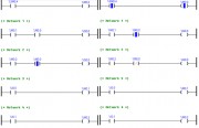 [/url] [/url]
Case #2
[url=http://www.99poze.ro/p/867bc172839600e6168139d41d630297.jpg]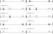 [/url] [/url]
Case #3
[url=http://www.99poze.ro/p/199fa30ac8a6d47bf51c3989748fde3d.jpg]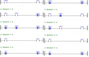 [/url] [/url] |
|
| Back to top |
|
 |
huyndog
Junior
Joined: 29 Mar 2022
Posts: 1
|
| Posted: 24/04/2022 12:54 Post subject: Re: Output polarity selection |
|
|
| franciscoazzad wrote: | Hello to everyone. Nice to meet you all. How are you? I hope you are doing well.
I’m developing a program with the purpose of make something similar to a pulse train in the output. However, sometimes I need the output to be a “positive” pulse and sometimes a “negative” one. By positive and negative I mean the polarity in relation to the pulse train source.
I’m trying to use a pair of bits in order to switch between the two choices of polarities. I attach a simplified version of the ladder diagram I’ve made. When I thought about the logic, it seemed logical to me, however, it isn’t working as supposed.
SM0.4 is a pulse train source. According to the software manual, it is a pulse train with 50% duty cycle and a cycle time of 2 s. That it to say it says at TRUE for one second and return to FALSE for another second. I assign the value of that variable bit to the M0.0 memory bit. I get the negative version of the pulse train logically negating it in the Network #2.
I assign the value of two inputs, I0.0 and I0.1, to other two memory bits, M0.1 and M0.2.
· When both inputs are in a FALSE state, the output stays FALSE, disregarding the state of SM0.4. (Case #1)
· When I0.0 is TRUE, M0.1 is TRUE. However, Q0.0 stays at FALSE no matter SM0.4 is TRUE or FALSE. I attach a pair of pictures. (Case #2)
· On the other side, when I0.1 is TRUE, M0.2 is TRUE. In this case, the output shows the correct behavior. It is the negated version of the pulse train source. (Case #3)
Has any of you experienced something similar? Is there a better way to execute my purpose?
I’m not executing the program, just simulating it with KincoBuilder from Kinco. However, it has always worked fine for me.
Thanks for you attention. I look forward for your responses.
Kind regards!
Case #1
[url=http://www.99poze.ro/p/8f811433a885d01ebcc2be267818258d.jpg][/url]
Case #2
[url=http://www.99poze.ro/p/867bc172839600e6168139d41d630297.jpg][/url]
Case #3
[url=http://www.99poze.ro/p/199fa30ac8a6d47bf51c3989748fde3d.jpg][/url] |
What programming environment do you use?
It's not clear. |
|
| Back to top |
|
|
franciscoazzad
Junior
Joined: 19 Apr 2022
Posts: 2
|
| Posted: 03/05/2022 13:35 Post subject: |
|
|
Hello!
I was using KincoBuilder, the programming software from Kinco.
Thanks for your response. I could solve the issue introducing some OR operations. I was involved in something called the "double coil syndrom''.
Regards! |
|
| Back to top |
|
|
|
|
You cannot post new topics in this forum
You cannot reply to topics in this forum
You cannot edit your posts in this forum
You cannot delete your posts in this forum
You cannot vote in polls in this forum
|
Powered by phpBB © 2001, 2005 phpBB Group
Fa-ti si tu propriul forum GRATUIT, pe www.myforum.ro |
 FAQ
FAQ Search
 Memberlist
 Usergroups
 Register
 Profile
 Log in to check your private messages
 Log in


